I don’t understand how to use your script.
I’ve tried add edge [edgeType=curved ]; in dot file and after I run gvpr -f alterSimpleEdge.gvpr tmp.dot I get:
/////////////////////////////////////////////////////////
// DIR: 1
// edge: A->D   >s,0,0 e,300,0 0,0              0,100 150,100 150,0             150,-100  300,-100 300,0<<
//  ti: 1  point: 300,0
//  ti: 2  point: 300,-100
//  ti: 3  point: 150,-100
//  ti: 4  point: 150,0
//  ti: 5  point: 150,100
//  ti: 6  point: 0,100
//  ti: 7  point: 0,0
//  ti: 8  point: e,300,0
// before: >s,0,0
// after: >e,0,0
//FIXED backwards arrowhead
// 0  e,0,0
//  arrowhead : e,0,0
// END: 0   START: 1
//   0  e,0,0  0  0
// 1  300,0
//   1  300,0  300  0
// 2  300,-100
//   2  300,-100  300  -100
// 3  150,-100
//   3  150,-100  150  -100
// 4  150,0
//   4  150,0  150  0
// 5  150,100
//   5  150,100  150  100
// 6  0,100
//   6  0,100  0  100
// 7  0,0
//   7  0,0  0  0
// 8  e,300,0
//  arrowhead : e,300,0
// END: 8   START: 1
//   8  e,300,0  300  0
//  tail2headDeltaX: 0    tail2headDeltaY: 0
//  arrow e  0
//   ArrowStart: 1  nextToarrowStart: 2  nextToarrowEnd: 8   arrowEnd: 8
// DISTANCE: 0
//  setting edgeOffset to default of 36 points (.5 inches)
gvpr:
 -- floating divide by 0
and I don’t understand what should I do with this.
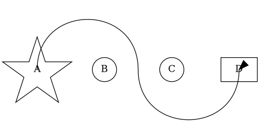
I expected to get something like this:
digraph G {
	A [pos="0,0!", shape=star];
	B [pos="100,0!", shape=circle];
	C [pos="200,0!", shape=circle];
	D [pos="300,0!", shape=box];

	A -> D [
		pos="e,298,-15 10,30 \
		30,100 150,100 150,0 \
		150,-100  300,-100 297,-20"
	];
/* pos in source for comparizon:
		pos="s,0,0 e,300,0 0,0 \
		0,100 150,100 150,0 \
		150,-100  300,-100 300,0"
*/
}
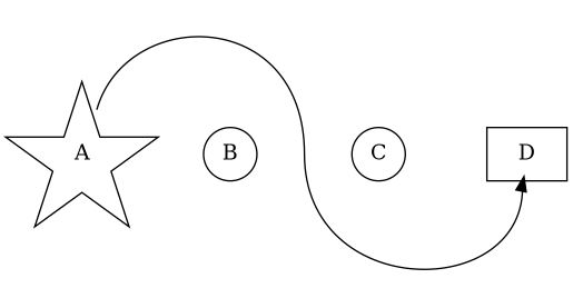
but more accurate
I need something in between
neato -n1 and
neato -n2