I noticed some inconsistencies when splines is set to true and I hope to find some guidance here. My main problem is that I would like to have a curved edge for one of my edges. I have learned that this can be achieved by putting invisible edges between the corresponding nodes so that the visible edge curves around them. This has worked in some of my diagrams but not in others that are built in the same way but where the arrangement of nodes is different.
Somewhat related, I noticed that the curving of edges around nodes that are in their way is not working when there are any overlapping nodes in the diagram.
Any ideas how to solve this? I have tried in DiagrammeR and in Windows command line. There is no difference whether I set overlap to true or false.
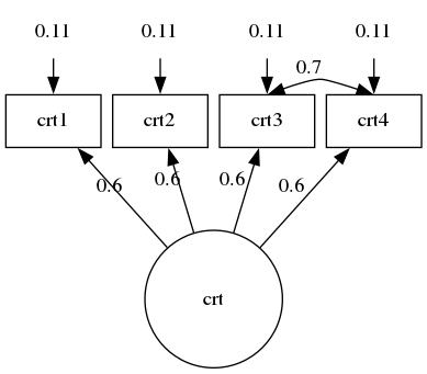
This is the code that I use wherethe curving of a single edge works:
digraph {

  graph [layout = neato,
  overlap = false,
  outputorder = edgesfirst
  splines=true ///curved  // better than true??
  ]

  node [shape = rectangle]

# Error Certainty
crt1e[pos = "11.1,  15!",  label = "0.11", width = 0.9, shape = none]
crt2e[pos = "12.3,  15!",  label = "0.11", width = 0.9, shape = none]
crt3e[pos = "13.5,  15!",  label = "0.11", width = 0.9, shape = none]
crt4e[pos = "14.7,  15!",  label = "0.11", width = 0.9, shape = none]

# Certainty
crt1 [pos = "11.1,  14!",  label = "crt1", width = 0.9]
crt2 [pos = "12.3,  14!",  label = "crt2", width = 0.9]
crt3 [pos = "13.5,  14!",  label = "crt3", width = 0.9]
crt4 [pos = "14.7,  14!",  label = "crt4", width = 0.9]

# Latent Certainty
crt  [pos = "12.9,  12!",  label = "crt",  width = 1.3, shape = circle]

# Path Certainty
crt->crt1 [label = "0.6"]
crt->crt2 [label = "0.6"]
crt->crt3 [label = "0.6"]
crt->crt4 [label = "0.6"]

# Covariance
crt3:n->crt4:n[label = "", style=invis constraint = false]
crt3:n->crt4:n[label = "", style=invis constraint = false]
crt3:n->crt4:n[label = "", style=invis constraint = false]
crt3:n->crt4:n[label = "0.7", dir = both, constraint = false]

# Error Path
crt1e->crt1
crt2e->crt2
crt3e->crt3
crt4e->crt4
}
This is the code where the curved edge for crt3:e->crt4e-> is not working:
grViz("digraph {

graph [layout = neato,
outputorder = edgesfirst,
# overlap = false,
splines = true]

node [shape = rectangle, width = 0.7, height = 0.3]

# Nodes
eu   [pos = '-1,  5!',  width = 1.3, shape = circle]
nrm  [pos = '-1,  0!', width = 1.3, shape = circle]
inf  [pos = '-3, 6.5!', width = 1.3, shape = circle]
cns  [pos = '-3, 3.5!', width = 1.3, shape = circle]

clr  [pos = '6, 5!', width = 1.3, shape = circle]
crt  [pos = '6, 2.5!', width = 1.3, shape = circle]
cor  [pos = '6, 0!', width = 1.3, shape = circle]

inf1 [pos = '-5, 7.5!']
inf2 [pos = '-5, 7!']
inf3 [pos = '-5, 6.5!']
inf4 [pos = '-5, 6!']
inf5 [pos = '-5, 5.5!']

cns1 [pos = '-5, 4.25!']
cns2 [pos = '-5, 3.75!']
cns3 [pos = '-5, 3.25!']
cns4 [pos = '-5, 2.75!']

nrm1 [pos = '-5, 1.5!']
nrm2 [pos = '-5, 1!']
nrm3 [pos = '-5, 0.5!']
nrm4 [pos = '-5, 0!']
nrm5 [pos = '-5, -0.5!']
nrm6 [pos = '-5, -1!']
nrm7 [pos = '-5, -1.5!']

clr1 [pos = '10, 5.75!']
clr2 [pos = '10, 5.25!']
clr3 [pos = '10, 4.75!']
clr4 [pos = '10, 4.25!']

crt1 [pos = '10, 3.25!']
crt2 [pos = '10, 2.75!']
crt3 [pos = '10, 2.25!']
crt4 [pos = '10, 1.75!']

cor1 [pos = '10, 0.5!']
cor2 [pos = '10, 0!']
cor3 [pos = '10, -0.5!']

inf1e[pos = '-6, 7.5!', shape = none, label = '2.12', width = 0.05]
inf2e[pos = '-6, 7!', shape = none, label = '2.12', width = 0.05]
inf3e[pos = '-6, 6.5!', shape = none, label = '2.12', width = 0.05]
inf4e[pos = '-6, 6!', shape = none, label = '1.12', width = 0.05]
inf5e[pos = '-6, 5.5!', shape = none, label = '1.12', width = 0.05]

cns1e[pos = '-6, 4.25!', shape = none, label = '1.12', width = 0.05]
cns2e[pos = '-6, 3.75!', shape = none, label = '1.12', width = 0.05]
cns3e[pos = '-6, 3.25!', shape = none, label = '1.12', width = 0.05]
cns4e[pos = '-6, 2.75!', shape = none, label = '1.12', width = 0.05]

nrm1e[pos = '-6, 1.5!', shape = none, label = '1.12', width = 0.05]
nrm2e[pos = '-6, 1!', shape = none, label = '1.12', width = 0.05]
nrm3e[pos = '-6, 0.5!', shape = none, label = '1.12', width = 0.05]
nrm4e[pos = '-6, 0!', shape = none, label = '1.12', width = 0.05]
nrm5e[pos = '-6, -0.5!', shape = none, label = '1.12', width = 0.05]
nrm6e[pos = '-6, -1!', shape = none, label = '2.12', width = 0.05]
nrm7e[pos = '-6, -1.5!', shape = none, label = '1.12', width = 0.05]

clr1e[pos = '11, 5.75!', shape = none, label = '3.12', width = 0.05]
clr2e[pos = '11, 5.25!', shape = none, label = '3.12', width = 0.05]
clr3e[pos = '11, 4.75!', shape = none, label = '3.12', width = 0.05]
clr4e[pos = '11, 4.25!', shape = none, label = '3.12', width = 0.05]

crt1e[pos = '11, 3.25!', shape = none, label = '2.12', width = 0.05]
crt2e[pos = '11, 2.75!', shape = none, label = '2.12', width = 0.05]
crt3e[pos = '11, 2.25!', shape = none, label = '2.12', width = 0.05]
crt4e[pos = '11, 1.75!', shape = none, label = '2.12', width = 0.05]

cor1e[pos = '11, 0.5!', shape = none, label = '2.12', width = 0.05]
cor2e[pos = '11, 0!', shape = none, label = '2.12', width = 0.05]
cor3e[pos = '11, -0.5!', shape = none, label = '2.12', width = 0.05]

# Edges
eu->inf [taillabel = '0.27', labeldistance = 5, labelangle = -15]
eu->cns [taillabel = '0.37', labeldistance = 3.5, labelangle = -25]

inf->inf1 [label = '0.67']
inf->inf2 [label = '0.56']
inf->inf3 [label = '0.45']
inf->inf4 [label = '0.34']
inf->inf5 [label = '0.23']

cns->cns1 [label = '0.34']
cns->cns2 [label = '0.45']
cns->cns3 [label = '0.56']
cns->cns4 [label = '0.67']

nrm->nrm1 [label = '0.56']
nrm->nrm2 [label = '0.45']
nrm->nrm3 [label = '0.34']
nrm->nrm4 [label = '0.45']
nrm->nrm5 [label = '0.56']
nrm->nrm6 [label = '0.78']
nrm->nrm7 [label = '0.67']

crt->crt1 [label = '0.89']
crt->crt2 [label = '0.90']
crt->crt3 [label = '0.89']
crt->crt4 [label = '0.78']

clr->clr1 [label = '0.67']
clr->clr2 [label = '0.56']
clr->clr3 [label = '0.45']
clr->clr4 [label = '0.34']

cor->cor1 [label = '0.23']
cor->cor2 [label = '0.34']
cor->cor3 [label = '0.56']

eu->nrm [dir = both, label = '.45 ']
eu->clr [dir = both, label = '-.45']
eu->crt [dir = both, taillabel = '-.46', labeldistance = 12, labelangle = 5]
eu->cor [dir = both, taillabel = '-.34', labeldistance = 12, labelangle = 5]
nrm->crt [dir = both, taillabel = '-.23', labeldistance = 12, labelangle = 5]
nrm->clr [dir = both, taillabel = '-.12', labeldistance = 12, labelangle = 6]
nrm->cor [dir = both, label = '-.45']
crt->clr [dir = both, taillabel = '.57', labeldistance = 5, labelangle = -20]
cor->crt [dir = both, taillabel = '.23', labeldistance = 5, labelangle = -20]
clr->cor [dir = both, taillabel = '.36', labeldistance = 9, labelangle = -5]

inf1e->inf1
inf2e->inf2
inf3e->inf3
inf4e->inf4
inf5e->inf5

cns1e->cns1
cns2e->cns2
cns3e->cns3
cns4e->cns4

nrm1e->nrm1
nrm2e->nrm2
nrm3e->nrm3
nrm4e->nrm4
nrm5e->nrm5
nrm6e->nrm6
nrm7e->nrm7

crt1e->crt1
crt2e->crt2
crt3e->crt3
crt4e->crt4

clr1e->clr1
clr2e->clr2
clr3e->clr3
clr4e->clr4

cor1e->cor1
cor2e->cor2
cor3e->cor3

crt3:e->crt4:e [dir = both, label = '.46']
crt3:e->crt4:e [dir = both, label = '.46']
crt3:e->crt4:e [dir = both, label = '.46']
crt3:e->crt4:e [dir = both, label = '.46']
crt3:e->crt4:e [dir = both, label = '.46']

}")

And this is what happens when I introduce an unrelated overlapping node. I add this node that overlaps with inf1: # Overlapping node on [pos = '-5, 7.5!', label = '1ßß']
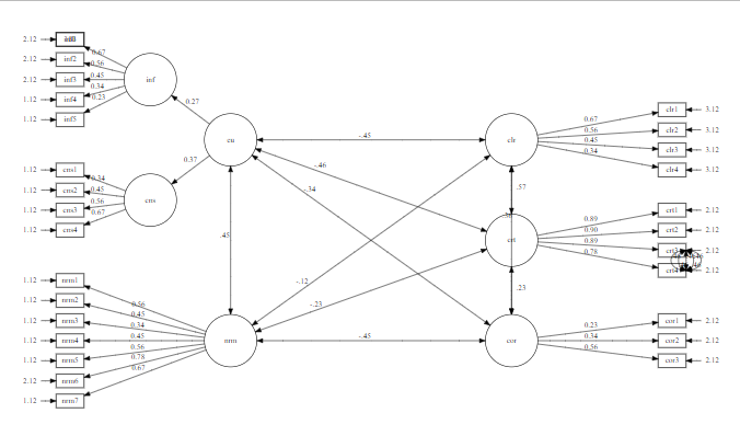
Interestingly, this solves my problem with the edge crt3->crt4 but now the edge clr->cor crosses right through crt without any curvature. How can I have both?