# Binary Tree: Force lonely node to be left or right
**URL:** https://forum.graphviz.org/t/binary-tree-force-lonely-node-to-be-left-or-right/1159
**Category:** Help
**Created:** [May 8, 2022, 5:32pm UTC](https://forum.graphviz.org/t/binary-tree-force-lonely-node-to-be-left-or-right/1159 "2022-05-08T17:32:27Z")
**Posts on this page:** 13
**Page:** 1
### Author:  [@ElectricHamster](https://forum.graphviz.org/u/ElectricHamster)
#### Post date: [May 8, 2022, 5:32pm UTC](https://forum.graphviz.org/t/binary-tree-force-lonely-node-to-be-left-or-right/1159/1 "2022-05-08T17:32:27Z")
Hey guys,
Im trying to make a binary tree with Graphviz (dot).
This is my simple code so far:
```auto
graph{
node [shape=circle]
1 -- 2;
2 -- 5;
2 -- 4;
5 -- 7;
7 -- 6;
6 -- 13;
13 -- 11;
11 -- 12;
12 -- 14;
4 -- 8;
4 -- 3;
3 -- 9;
9 -- 10;
}
```
And this is the ouput:

So what I want to get is that for example node 2 is the left child from node 1, and node 7 is the right child node of node 5.
I tried it with “empty” nodes (style = none, color = white) but it still had those straight downward edges.
I want it to look like a nice and smooth binary tree, where you can see what is a right and left child (even if the child is single).
Hope you can help me to get this style I want 😃
Thank you
---
### Author:  [@steveroush](https://forum.graphviz.org/u/steveroush)
#### Post date: [May 8, 2022, 8:02pm UTC](https://forum.graphviz.org/t/binary-tree-force-lonely-node-to-be-left-or-right/1159/2 "2022-05-08T20:02:59Z")
Would you sketch out what you are looking for - by hand is fine. (If you wanted a classical tree shape, it might be ~128 nodes wide)
---
### Author:  [@ElectricHamster](https://forum.graphviz.org/u/ElectricHamster)
#### Post date: [May 8, 2022, 8:43pm UTC](https://forum.graphviz.org/t/binary-tree-force-lonely-node-to-be-left-or-right/1159/3 "2022-05-08T20:43:52Z")
This is what I want (didnt draw all nodes I need)
You see, in this tree clearly left and right nodes. Even if the nodes have no siblings.
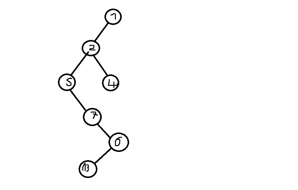
In the tree I created with dot the edges are straight downward. And I need left and right nodes everytime.
---
### Author:  [@steveroush](https://forum.graphviz.org/u/steveroush)
#### Post date: [May 9, 2022, 5:36pm UTC](https://forum.graphviz.org/t/binary-tree-force-lonely-node-to-be-left-or-right/1159/4 "2022-05-09T17:36:21Z")
Unfortunately, Graphviz does not include a tree model (see [How to lay out binary tree / hierarchicy? - #3 by steveroush](https://forum.graphviz.org/t/how-to-lay-out-binary-tree-hierarchicy/610/3) and [Provide a collection of simple tree layouts (#2032) · Issues · graphviz / graphviz · GitLab](https://gitlab.com/graphviz/graphviz/-/issues/2032)).
However, here is a post-processor program for binary trees (not well tested). It is pretty simple-minded, defaulting to _single-edges-always-go-left_ rule. (_single-edges-always-go-right_ is equally easy). The problem with these simple rules is that they tend to be very lop-sided (see bottom).
To allow for more symmetric layouts, the post-processor allows the user to explicitly direct an edge right or left using a new edge attribute: **side**. Values: _L|l|R|r|U|u|D|d_
The post-processor is written in the **GVPR** ([https://www.graphviz.org/pdf/gvpr.1.pdf](https://www.graphviz.org/pdf/gvpr.1.pdf)) language - part of the Graphviz package. The **GVPR** output is passed to `neato -n` (see [FAQ | Graphviz](https://graphviz.org/faq/#FaqDotWithNodeCoords)). Somewhat convoluted, but you should not have to mess with anything other than your input.
Command-line (Linux) (Windows should be similar):
`dot -Tdot myfile.gv | gvpr -c -f binaryTree.gvpr | neato -n -Tpng >myfile.png`
binaryTree.gvpr:
```auto
BEGIN{
int left_right, Right[], Left[];
float shiftFactor;
node_t Head, Tail;
}
BEG_G{
left_right=0;
if ((hasAttr($G, "rankdir")) && ($G.rankdir!="") && $G.rankdir=="@(LR|RL)") left_right = 1;
shiftFactor=1.1*72; // effectively sets the angle (eyeballed, no trig)
}
E{
Head=$.head;
Tail=$.tail;
// legal values for side: left(L|l) or right(R|r) or up(U|u) or down(D|d)
// current value testing is incomplete
// awkwardly written, but seemingly correct
if (Left[Tail]!=1 && (((!((hasAttr($, "side")) && ($.side!=""))) || Right[Tail]==1 || ((hasAttr($, "side")) && ($.side!="") && $.side=="@(L|l|D|d)")))){
print("// LEFT/UP");
Left[Tail]=1;
if (left_right==0)
Head.pos=(string)(Tail.X-(shiftFactor*(float)Head.width)) + "," + (string)Head.Y;
else
Head.pos=(string)Head.X + "," + (string)(Tail.Y-(shiftFactor*(float)Head.height)) ;
}else{
print("// RIGHT/DOWN");
Right[Tail]=1;
if (left_right==0)
Head.pos=(string)(Tail.X+(shiftFactor*(float)Head.width)) + "," + (string)Head.Y;
else
Head.pos=(string)Head.X + "," + (string)(Tail.Y+(shiftFactor*(float)Head.height)) ;
}
$.pos="";
}
```
Your file, modified:
```auto
graph{
node [shape=circle]
1 -- 2;
2 -- 5;
2 -- 4;
5 -- 7;
7 -- 6;
6 -- 13 [side=R] // added a new attribute (side), send this edge to the right
13 -- 11;
11 -- 12 [side=R] // this edge to the right
12 -- 14;
4 -- 8;
4 -- 3;
3 -- 9;
9 -- 10 [side=R] // this edge to the right
}
```
Giving:

Default (lop-sided) version from the program:

---
### Author:  [@lu5m](https://forum.graphviz.org/u/lu5m)
#### Post date: [January 6, 2024, 9:05am UTC](https://forum.graphviz.org/t/binary-tree-force-lonely-node-to-be-left-or-right/1159/5 "2024-01-06T09:05:12Z")
thank you for your great work!
however, i encounter a overlapping problem like below, how to solve?
```auto
graph {
node [shape=circle];
a--b;
b--d;
d--g [side=R];
b--e [side=R];
a--c [side=R];
c--f;
}
```

---
### Author:  [@steveroush](https://forum.graphviz.org/u/steveroush)
#### Post date: [January 6, 2024, 4:25pm UTC](https://forum.graphviz.org/t/binary-tree-force-lonely-node-to-be-left-or-right/1159/6 "2024-01-06T16:25:58Z")
First an answer to your question:
```auto
graph {
node [shape=circle];
a--b;
b--d;
d--g [side=R];
b--e [side=R];
a--c [side=R];
c--f [side=R] // flipped to the right side
}
```
Giving:

I’ve been laughing at my program all morning. Note that I did say:
```auto
(not well tested). It is pretty simple-minded
```
This program is very simple-minded and not even close to being a general-purpose binary-tree program. OK for some sparse binary-trees, but that is it. (Think about the case of B and C each having two children).
I assume that somewhere there good heuristics for this problem. Maybe sometime one will be coded up for Graphviz.
---
### Author:  [@lu5m](https://forum.graphviz.org/u/lu5m)
#### Post date: [January 7, 2024, 3:51am UTC](https://forum.graphviz.org/t/binary-tree-force-lonely-node-to-be-left-or-right/1159/7 "2024-01-07T03:51:51Z")
inspired by [Visualising a Binary Search Tree using GraphViz « devjeetr](https://devjeetr.wordpress.com/2012/04/30/visualising-a-binary-search-tree-using-graphviz/) , got a simpler solution.
- adding empty nodes( shaped as point) to represent empty siblings;
- relying on graphviz to handle the possible overlapping issue.
- not as pretty as above, but simple and sufficient.
```dot
graph {
node [shape=circle];
a--b;
b--d;
d_NULL_LEFT [shape=point];
d--d_NULL_LEFT;
d--g;
g_NULL_LEFT [shape=point];
g--g_NULL_LEFT;
g_NULL_RIGHT [shape=point];
g--g_NULL_RIGHT;
b--e;
e_NULL_LEFT [shape=point];
e--e_NULL_LEFT;
e_NULL_RIGHT [shape=point];
e--e_NULL_RIGHT;
a--c;
c--f;
f_NULL_LEFT [shape=point];
f--f_NULL_LEFT;
f_NULL_RIGHT [shape=point];
f--f_NULL_RIGHT;
c_NULL_RIGHT [shape=point];
c--c_NULL_RIGHT;
}
```

---
### Author:  [@jayaprabhakar](https://forum.graphviz.org/u/jayaprabhakar)
#### Post date: [August 30, 2024, 9:53pm UTC](https://forum.graphviz.org/t/binary-tree-force-lonely-node-to-be-left-or-right/1159/8 "2024-08-30T21:53:46Z")
I found a slightly more reliable way. I’m am working on formal methods system ([fizzbee.io](http://fizzbee.io)) to validate distributed systems and algorithms, and I also have visualization feature, so I need a way to visualize a tree.
For trees that are sparse with too many nodes having a single child, the easiest and visually pleasing is add hidden nodes, and weights to get good alignment following this algorithm.
1. If a node has both left and right children, add another node say M1 as the middle child, with weight=2. This will increase the probability the M1 node will be directly under the node1. (Add :s direction as well to tail edge)
2. If a node only has left child, add a node R1 after the left edge. and weight=2 and direction :s
3. If a node only has right child, add a node L1 before the right edge and and weight=2 and direction :s
```auto
digraph{
node [shape=circle]
splines=false
1 -> 2 [arrowhead=none];
1:s -> R1 [weight=2 style=invisible arrowhead=none];
2 -> 5 [arrowhead=none];
2:s -> M1 [weight=2 style=invisible arrowhead=none];
2 -> 4 [arrowhead=none];
5 -> 7 [arrowhead=none];
5:s -> R5 [weight=2 style=invisible arrowhead=none];
7 -> 6 [arrowhead=none];
7:s -> R7 [weight=2 style=invisible arrowhead=none];
6:s -> L6 [weight=2 style=invisible arrowhead=none];
6 -> 13 [side=R arrowhead=none] // added a new attribute (side), send this edge to the right
13 -> 11 [arrowhead=none];
13:s -> R13 [weight=2 style=invisible arrowhead=none]
11 -> 12 [side=R arrowhead=none] // this edge to the right
11:s -> L11 [weight=2 style=invisible arrowhead=none];
12 -> 14 [arrowhead=none];
12:s -> R12 [weight=2 style=invisible arrowhead=none]
4 -> 8 [arrowhead=none];
4:s -> M4 [weight=2 style=invisible arrowhead=none]
4 -> 3 [arrowhead=none];
3 -> 9 [arrowhead=none];
3:s -> R3 [weight=2 style=invisible arrowhead=none];
9 -> 10 [side=R arrowhead=none] // this edge to the right
9:s -> L9 [weight=2 style=invisible arrowhead=none]
R1 [style=invisible label=""]
R5 [style=invisible label=""]
R7 [style=invisible label=""]
R13 [style=invisible label=""]
R12 [style=invisible label=""]
R3 [style=invisible label=""]
L6 [style=invisible label=""]
L11 [style=invisible label=""]
L9 [style=invisible label=""]
M1 [style=invisible label=""]
M4 [style=invisible label=""]
R5 -> 7 [arrowhead=vee constraint=false label="i"]
M4 -> 8 [arrowhead=vee constraint=false label="index1"]
}
```
[dot]
digraph{
node [shape=circle]
splines=false
1 → 2 [arrowhead=none];
1:s → R1 [weight=2 style=invisible arrowhead=none];
2 → 5 [arrowhead=none];
2:s → M1 [weight=2 style=invisible arrowhead=none];
2 → 4 [arrowhead=none];
5 → 7 [arrowhead=none];
5:s → R5 [weight=2 style=invisible arrowhead=none];
7 → 6 [arrowhead=none];
7:s → R7 [weight=2 style=invisible arrowhead=none];
6:s → L6 [weight=2 style=invisible arrowhead=none];
6 → 13 [side=R arrowhead=none] // added a new attribute (side), send this edge to the right
13 → 11 [arrowhead=none];
13:s → R13 [weight=2 style=invisible arrowhead=none]
11 → 12 [side=R arrowhead=none] // this edge to the right
11:s → L11 [weight=2 style=invisible arrowhead=none];
12 → 14 [arrowhead=none];
12:s → R12 [weight=2 style=invisible arrowhead=none]
4 → 8 [arrowhead=none];
4:s → M4 [weight=2 style=invisible arrowhead=none]
4 → 3 [arrowhead=none];
3 → 9 [arrowhead=none];
3:s → R3 [weight=2 style=invisible arrowhead=none];
9 → 10 [side=R arrowhead=none] // this edge to the right
9:s → L9 [weight=2 style=invisible arrowhead=none]
R1 [style=invisible label=“”]
R5 [style=invisible label=“”]
R7 [style=invisible label=“”]
R13 [style=invisible label=“”]
R12 [style=invisible label=“”]
R3 [style=invisible label=“”]
L6 [style=invisible label=“”]
L11 [style=invisible label=“”]
L9 [style=invisible label=“”]
M1 [style=invisible label=“”]
M4 [style=invisible label=“”]
R5 → 7 [arrowhead=vee constraint=false label=“i”]
M4 → 8 [arrowhead=vee constraint=false label=“index1”]
}
[/dot]
One big issue with this solution is adding any edge from outside the graph to a node will easily mess up the visual. So any link you have should have constraint=false.
I wanted to also, show a variable i refers to a specific node. Instead of adding a new node, that messes up the design, I see adding a link from the hidden nodes M\*, L\*, R\* makes it look better.
* * *
Another option, if you really want the nodes to be placed correctly, or when the graph is mostly full, using a table works. But has a few drawbacks.
1. The style can only be a box.
2. The edges must be drawn separately with a javascript (or any other SVG editor API).
The biggest advantage is, the tree will look like a tree irrespective of other nodes in the system.
```auto
digraph {
tree [shape=plaintext class="fizzbee binarytree" label=<
| | | | | | | | 0 | | | | | | | |
| | | | 1 | | | | | | | | 2 | | | |
| | 3 | | | | 4 | | | | 5 | | | | 6 | |
| 7 | | 8 | | 9 | | 10 | | 11 | | 12 | | 13 | | 14 |
>]
tree:0:sw -> tree:1:ne [constraint="false" class="fizzbee binarytree edge"]
}
```
---
### Author:  [@jayaprabhakar](https://forum.graphviz.org/u/jayaprabhakar)
#### Post date: [August 30, 2024, 10:55pm UTC](https://forum.graphviz.org/t/binary-tree-force-lonely-node-to-be-left-or-right/1159/9 "2024-08-30T22:55:36Z")
A related minor question. Is there a way to not include a node from being ranked, like constraint=false for edge, is there a way to set that to a node.
I frequently face an issue adding an arrow, but that requires a hidden node. Adding the hidden node almost always messes up with the layout. That I need to tune things again.
It would be nice if we could have a real headless or tailless edge.
---
### Author:  [@steveroush](https://forum.graphviz.org/u/steveroush)
#### Post date: [August 31, 2024, 7:48pm UTC](https://forum.graphviz.org/t/binary-tree-force-lonely-node-to-be-left-or-right/1159/10 "2024-08-31T19:48:28Z")
The only way I can think of is to either explicitly position all your nodes and then use **neato -n** to just position edges or exclude your “troublesome” edges until after **dot** has positioned the rest of the nodes. Then add the “troublesome” edges in a later step.
Technically, you can create headless/tailless edges (see below), but somehow the start and end of the edge have to be defined - if not by terminating nodes, by terminating positions and/or lengths & angles.
Here is a graph with only one node, and 7 edges that reference the node, but do not touch it.
```auto
digraph cheat{
layout=nop2 // where is this documented these days ??
lonelyNode [shape=triangle color=green label="" pos="10,167"]
lonelyNode -> lonelyNode [dir=none color=red pos="25,25 25,25 75,25 75,25 "]
lonelyNode -> lonelyNode [dir=none color=darkgreen pos="65,65 65,65 195,65 195,65 "]
lonelyNode -> lonelyNode [dir=none color=purple pos="105,105 105,105 315,105 315,105 "]
lonelyNode -> lonelyNode [dir=none color=aqua pos="145,145 145,145 435,145 435,145 "]
lonelyNode -> lonelyNode [dir=none color=cyan pos="185,185 185,185 555,185 555,185 "]
lonelyNode -> lonelyNode [dir=none color=red pos="225,225 225,225 675,225 675,225 "]
lonelyNode -> lonelyNode [dir=none color=darkgreen pos="265,265 265,265 795,265 795,265 "]
}
```
Giving:

---
### Author:  [@jayaprabhakar](https://forum.graphviz.org/u/jayaprabhakar)
#### Post date: [September 1, 2024, 8:01pm UTC](https://forum.graphviz.org/t/binary-tree-force-lonely-node-to-be-left-or-right/1159/11 "2024-09-01T20:01:27Z")
I am trying this in [Graphviz visual editor](http://magjac.com/graphviz-visual-editor/) and in [viz-js](https://viz-js.com/) with neato layout engine, but they didn’t work. Does this need preprocessing as well or neato engines in these web tools don’t work?
---
### Author:  [@steveroush](https://forum.graphviz.org/u/steveroush)
#### Post date: [September 1, 2024, 8:57pm UTC](https://forum.graphviz.org/t/binary-tree-force-lonely-node-to-be-left-or-right/1159/12 "2024-09-01T20:57:07Z")
The documentation for **nop1** & **nop2** was hard to find.
([nop2 | Graphviz](https://www.graphviz.org/docs/layouts/nop2/))
The **nop2** layout engine is `neato -n2`
Add this line `layout=nop2 ` to the one-node graph and the javascript implementations work as suggested.
---
### Author:  [@smattr](https://forum.graphviz.org/u/smattr)
#### Post date: [September 3, 2024, 12:24am UTC](https://forum.graphviz.org/t/binary-tree-force-lonely-node-to-be-left-or-right/1159/13 "2024-09-03T00:24:23Z")
Note that AFAIK `nop2` was somewhat useless until [27dff4d8fbdfbdcac232c9f8e43ad4c790841e66](https://gitlab.com/graphviz/graphviz/-/commit/27dff4d8fbdfbdcac232c9f8e43ad4c790841e66) which landed in Graphviz 11.0.0. The visual editor is currently using Graphviz 12.1.0, but other versions of Graphviz you access may not be recent enough for this.